
Bahnhof Groningen, Phase 2
Short description
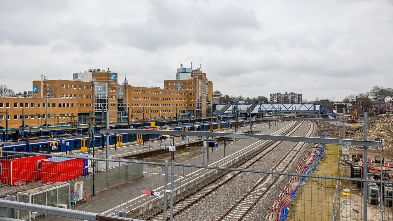
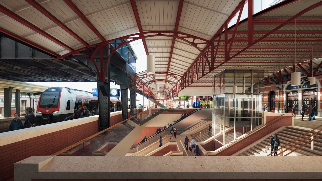
The project involves the complete conversion of the station area with the aim of promoting attractive urban development, including the southern districts of the city. This primarily involves the expansion of public transport systems such as trains, buses and, last but not least, bicycles.
The project
The former use of the southern part of the site as a stabling area for trains was no longer required in this size and was rebuilt elsewhere in Groningen in line with current requirements. The site thus freed up was redeveloped and prepared for the relocation and expansion of the current bus station. In addition, a new entrance to the station and a connection to the southern part of the city can be created.
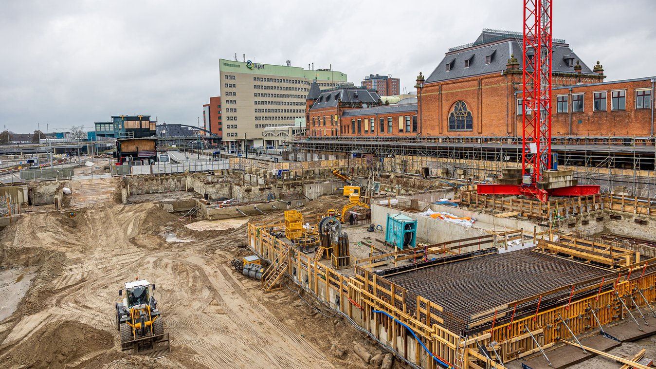
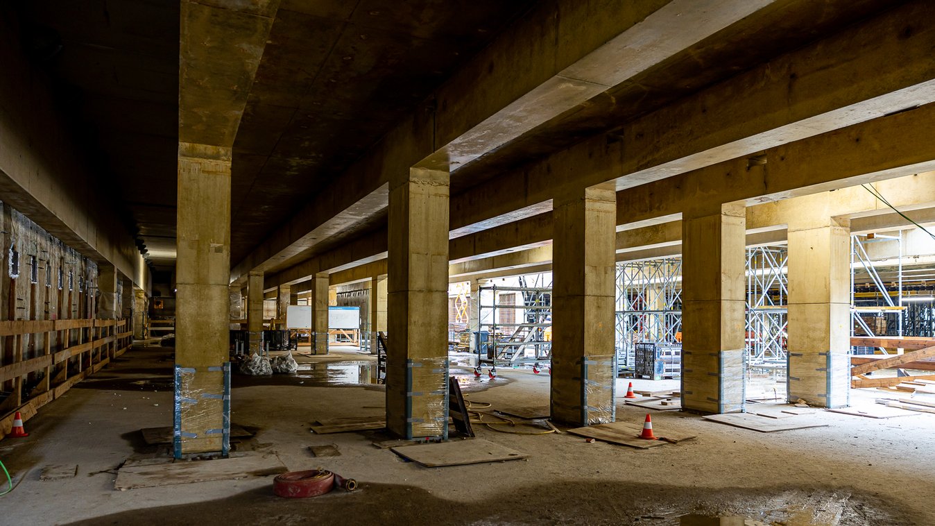
As part of the project to convert the station area in Groningen, a watertight excavation pit was created for an engineering structure with two basement levels. This requires permanent reinforced concrete diaphragm walls. These are held in place by a head beam and anchored with strand anchors. The special logistical situation, as well as the future construction, posed particular challenges during execution. Of particular note is the use of partially permanent Multibond strand anchors ® with up to 19 strands, which require special attention during handling and production.
Services in detail
Production and delivery of
- 18 pcs. 2-3x staggered anchors type BBV L12 to BBV L15 Multibond temporary with average lengths of 37.00m and average grouting distances of 12.00 - 19.50m as well as
- 35 triple-staggered permanent anchors type BBV Multibond MONO II L15 to L19 with lengths of up to 46.50m and average grouting distances of 19.50 - 21.00m
- Loads between 1,100 KN and 2,300 KN with 2-fold or 3-fold staggered Multibond anchors
Delivery of
- 35 electrical anchor load cells with load distribution plates, load range up to 2500 KN
- Readout device
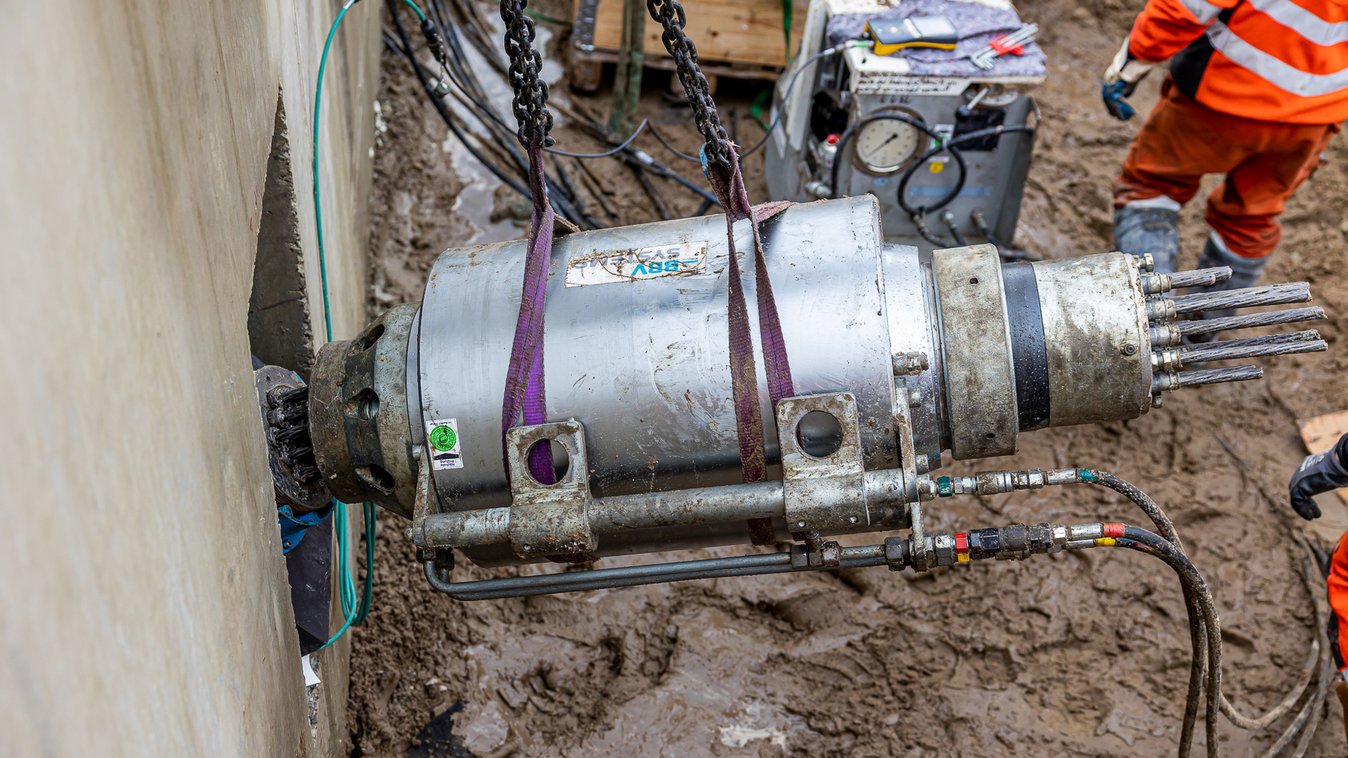
Supply and hire of special lifting equipment for handling strand permanent anchors supplied on drums and hire of BBV tensioning equipment and hydraulic units
Challenges
Adaptation of the production processes, taking into account the anchor dimensions and guaranteeing the quality assurance of the corrosion protection The required excavation pit with permanent and anchored diaphragm walls posed a number of challenges from a construction perspective. The building structure, consisting of permanent diaphragm walls and a solid head beam built during the construction of the excavation pit, which in turn represents the support for the later platform structure, required the use of highly stressed strand anchors.
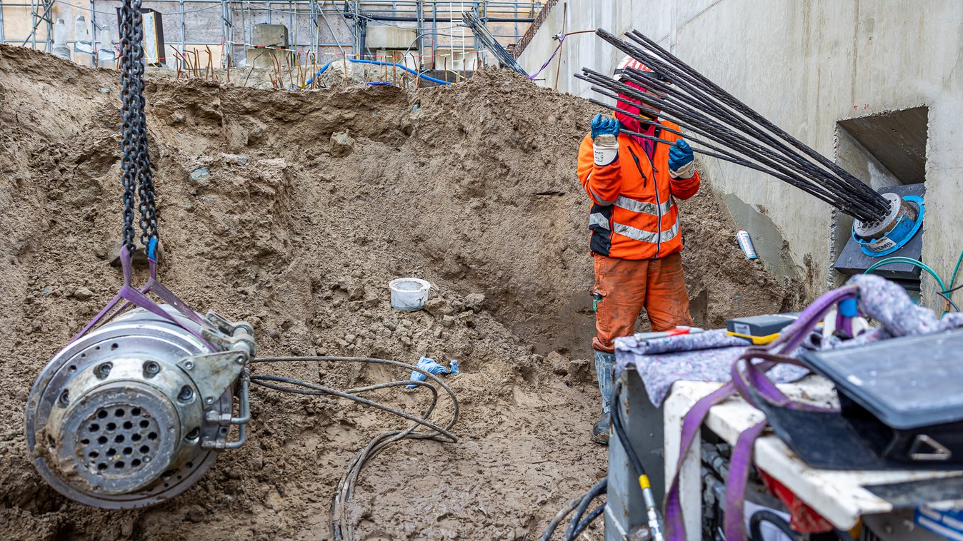
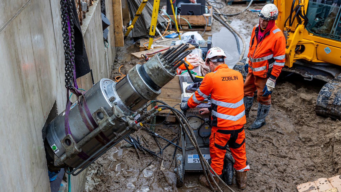
A special rolling device was used to install the permanent anchors from the spindles. The motor-driven device made it possible to unroll the anchor at a self-defined speed and install it in the borehole. Handling the device, which weighed around 5 tons, plus the drum with the anchor, which weighed up to 2 tons, was a challenge due to the limited space available.
Avoiding stray current corrosion Another requirement of the customer was to coat the anchor head construction against electrical conductivity and thus to avoid stray current corrosion. The requirement resulted from the permanent use of the anchors in areas underneath the tracks. Both the compensation plate, which lies between the head beam and the load cell, as well as the anchor plate itself with the connected pipe socket and the covers for the permanent anchor head were coated for this case. An insulating plate was used underneath the wedge beam so that the strands were not in direct contact with the accessible anchor head. Resistance measurements carried out on the anchor head by the client proved that the earthing worked.
Further information
A consortium consisting of the municipality and province of Groningen, the Dutch railroads (Nederlandse Spoorwegen), ProRail and the Dutch construction company Strukton are working together to redesign the entire station area.
For the project, the planner Strukton specified grouted anchors with grout body lengths of up to 18 meters in phase 1 and up to 21 meters in phase 2. With a conventional anchor, it makes economic sense to activate the grout body to a length of up to 7 meters. The greatest force transmission occurs in the first 2-3 meters. The effectiveness of the force transmission decreases with every additional meter. Conversely, this means that either the number of anchors must be increased and thus the anchor spacing reduced or an additional anchor layer is required. A third option is to use so-called staggered anchors.
With staggered anchors, an attempt is made to activate the "unused" part of the grout body with additional strands. In principle, two or more grouted anchors are produced with just one hole. The longer strands are produced with PE sheaths that extend into the grout body in order to ensure the free anchor length in the grout body. This allows the forces to be transferred to the deeper grout body area. The difficulty with conventional staggered anchors lies in the effort required to test and tension the grouted anchors. The different lengths of the individual strands also result in different moduli of elasticity, which makes conventional testing and tensioning of all strands of an anchor at the same time impossible. If an attempt were made to stress a staggered anchor in just one pass, the shorter strands would absorb more forces due to their higher stiffness. The necessary force would not be achieved with the long strands. In conclusion, the staggered anchors must be tested and tensioned after staggering.
BBV Systems has its own patented staggered anchor system. With the so-called BBV-multibond®, all strands are tested and tensioned simultaneously in a single pass. This means that errors in the stressing process can be avoided.
The excavation planning was drawn up by the client. The client provided staggered anchors for anchoring the surrounding diaphragm wall. Based on the implementation planning, a work plan was drawn up in cooperation between the contractors using BBV Multibond Anchors®. In addition to the staggering of the anchors, the stiffness of the anchors had to be taken into account. Regardless of the adjustment of the number of strands for the Multibond system, the planner insisted that the stiffness of the system should not deviate by more than ten percent. The factory planning was therefore carried out in two steps:
Step 1: Conversion of the staggered anchors into Multibond anchors.
Step 2: Consideration of the stiffness of the system.
Only the number of strands could be adjusted. It was not possible to change the anchor length due to the soil layers and the defined position of the grout body. In this case, the originally planned number of strands was increased from 15 to 18. The need for this was not due to the expected load, which could have been easily realized with the 15 strands, but due to the consideration of stiffness. The multiple strands also meant that the fixed load had to be adjusted. Each strand required a minimum fixed load of 60 kN so that the wedges could perform their function and prevent the strands from slipping. Thanks to open-ended communication between the parties involved in the planning, the work planning was completed to everyone's satisfaction.
The production of the total of 53 grouted anchors in phase 2 was demanding in terms of the logistical challenges, as 35 of them were designed as permanent multi-bond anchors. These had up to 19 strands, an anchor length of 45 m with a maximum grout body length of 21 m and were staggered 3 times. The test load amounted to 2,316 kN. As permanent anchors, the strands were encased in a ribbed tube with a diameter of 160 mm. Due to the great length, the anchors in the ribbed tube could not be pre-pressed, but had to be delivered on spindles. The ribbed tube was only grouted after installation in the borehole, before the outer cap grouting was carried out.